ABS Wheel Speed Sensor Detection
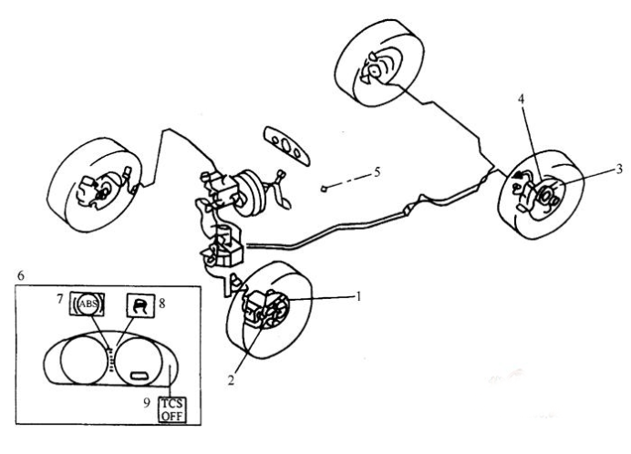
The components of ABS anti-lock braking system are installed as shown in Figure 1.

Fig. 1 Installation position of components in ABS/TCS electronic control system
Remove the wheel, check the installation of the wheel speed sensor, and clean the sensor induction terminal. If necessary, adjust the installation to make it work normally.
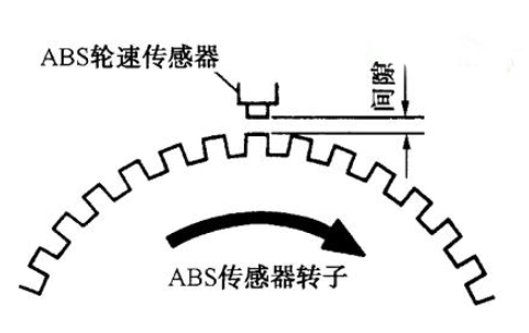
(2) The clearance between the sensor and the rotor should be 0.3-1.1 mm, as shown in Figure 2.
(3) Remove the sensor plug and check the resistance of the sensor. It should be 1.3-1.7k. Otherwise, the wheel speed sensor should be replaced.
Check the signal voltage. Lift the wheel to suspend the four wheels and remove the ABS sensor plug. Rotating the rotor at a speed of one turn per second and checking the output signal voltage should be between 0.25 and 1.2V (AC), otherwise, the ABS wheel speed sensor should be replaced.
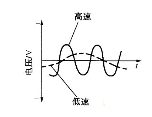
Check signal waveform. When rotating the wheel, the oscilloscope is used to check the output signal waveform of the sensor. As shown in Figure 3, if the waveform does not match Figure 3, the sensor should be replaced.

Figure 2 ABS Wheel Speed Sensor Clearance Check

Figure 3 ABS Wheel Speed Sensor Waveform Check


